

Key Takeaways
- Calculate the combined weight of the mold, rack, pallet, and attachments carried during transport.
- Check rack openings, support-leg spacing, underside clearance, and lifting contact points before confirming vehicle dimensions.
- Match the guidance method to route stability, floor conditions, and the frequency of layout changes.
- Review the complete pickup, transport, and delivery process rather than choosing a vehicle by load capacity alone.
Introduction
Moving large molds between storage racks, production areas, and processing stations requires more than sufficient load capacity. The load must remain stable, the vehicle must fit beneath or alongside the rack, and the lifting platform must reach the correct position for pickup and delivery.
A mold transfer cart should be selected around the complete handling task: what needs to be moved, where it starts and ends, how it is picked up, and what obstacles exist along the route.
What Types of Mold Transfer Carts Are Used in Industrial Manufacturing?
The main difference between transfer cart designs is how they move and handle the load. Buyers should first identify whether the task requires a fixed route, flexible movement, or vertical lifting.
Rail-Guided and Trackless Transfer Carts
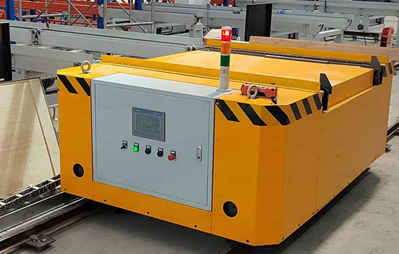
Rail-guided carts are designed for repeated movement between fixed stations. Rails define the travel path and help keep the vehicle aligned. They are suitable when the route is permanent and the cart does not need to serve many alternative destinations.
Trackless carts do not depend on floor rails. They can move between different work areas and are easier to accommodate when routes change. However, buyers need to check steering space, floor condition, and the vehicle’s guidance and control method.
For a permanent route between two production stations, rail guidance can provide a straightforward layout. If the vehicle must serve several areas or the workshop may be rearranged, a trackless design offers more flexibility.
Hydraulic Lifting Transfer Carts
A standard transfer cart carries a load at a fixed platform height. A hydraulic lifting design adds vertical movement, allowing the platform to raise or lower a mold during pickup and delivery.
The key question is whether the mold only needs horizontal transportation or must also be lifted to clear rack supports or align with another platform. If the mold is stored on a raised rack, measure the rack opening and the required lifting interface before deciding on the vehicle structure.
A lifting design is useful when the load needs to be raised clear of its supports. If the mold only moves between surfaces at the same height, a lifting mechanism may add cost and maintenance without solving a real handling problem.
AGV-Based Mold Transfer Systems
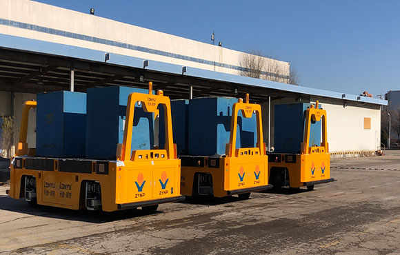
An automated guided vehicle moves along a defined route with limited need for continuous manual steering. Depending on the navigation method, its path may be established through magnetic guidance, floor markers, or laser-based mapping.
The main benefit is repeatable transport between known pickup and delivery points. Before choosing automated operation, buyers should confirm that the transport sequence can be defined clearly and that staff can keep the route accessible. Frequent unplanned destination changes or constantly blocked paths can make automated transport harder to manage.
If the main requirement is occasional movement with frequent changes to destinations, manual or remote operation may be more practical. Automation is more suitable when the same transport tasks recur and can be incorporated into a consistent production routine.
How Should Buyers Match Load Capacity and Mold Rack Dimensions?
A cart can have sufficient rated capacity and still be unsuitable if the mold is poorly supported or cannot fit through the rack opening. Weight and geometry need to be checked together.
Calculate the Total Weight of the Mold and Supporting Rack
Start with the heaviest mold the vehicle will carry. Add the weight of any pallet, rack, fixture, or attachment that travels with it. Do not use the mold’s weight alone if the supporting structure is also lifted.
Then check how the load is distributed. A mold with an offset center of gravity can place more force on one side of the platform. Confirm the center of gravity and support locations from the mold drawing or verified measurements.
The combined load must stay within the vehicle’s rated capacity, and the support arrangement must keep it stable. If the mold is asymmetrical or its weight is unevenly distributed, share the loading drawing with the supplier so the platform and support points can be reviewed together.
Check Rack Dimensions and Support-Leg Spacing
Measure the clear opening between rack legs, not just the rack’s overall width. Also record the distance between support members, the height of the underside, and any crossbars or braces that could obstruct entry.
Compare these measurements with the vehicle’s full outline, including wheels and other protruding parts. The vehicle must enter without contacting the rack supports. Its lifting platform must also reach the intended contact points without pushing against the rack structure.
Pay particular attention to the clear entry width, underside height, and space available for the lifting platform. A rack drawing that shows support-leg positions and internal dimensions helps identify interference before equipment is ordered.
Match Vehicle Dimensions to the Available Working Space
Measure the narrowest aisle, doorway, turning area, and approach to each pickup and delivery point. A vehicle’s overall length and width do not show whether it can complete a turn in a restricted area.
Mark the route on a floor plan and compare the manufacturer’s turning radius with the actual corner geometry. Include space for alignment at the rack and room for the vehicle to leave after loading.
The vehicle needs enough room to enter, turn, align, and exit at every station without relying on unplanned reversing or manual repositioning. If the route is too narrow, adjust the route or vehicle layout before ordering.
What Operating Conditions Should Buyers Check Before Selecting a Mold Transfer AGV?
After confirming load and rack compatibility, buyers need to check whether the vehicle can complete the full route and handoff. Navigation is only one part of this assessment.
Determine the Required Lifting Height and Positioning Accuracy
Measure the height difference between the vehicle platform and the mold’s support surface. Include the clearance needed to enter beneath the rack and the vertical travel needed to lift the mold clear of its supports.
The lifting interface matters as much as the height. Identify where the platform will contact the mold or its supporting rack. If the mold has several support points, check that the platform can engage them without placing pressure on weak or unsupported sections.
Positioning requirements depend on the handoff. A vehicle that stops near a storage area may not need the same accuracy as one that places a platform directly beneath a mold. Define the allowable alignment gap and the reference points used at each station.
Provide the pickup and delivery heights, rack clearance, support-point drawing, and required alignment tolerance to the supplier. These details help establish the necessary lifting stroke and stopping performance. Do not assume that all AGVs provide the same lifting or positioning capability.
Compare Magnetic Strip, QR Code, and Laser SLAM Navigation
Navigation should match route stability and the frequency of layout changes.
Magnetic guidance follows a physical route installed on the floor. It suits repeatable paths, but route changes may require modifications to the guidance layout. Buyers should consider floor installation and the work involved in changing the route.
QR-code navigation uses floor markers as position references. It can support defined routes and station points, but marker placement and condition affect reliability. Oil, dust, abrasion, or damaged markers may interfere with recognition, so the floor and maintenance routine need to be considered.
Laser SLAM uses environmental features to map and locate the vehicle. It can offer more route flexibility, although the environment must provide usable reference features. Large changes to the surroundings, extensive obstruction, or repetitive-looking areas may affect mapping and localization.
When specifying an agv automated guided vehicle system, compare route changes, station positioning, floor conditions, and guidance maintenance—not just the navigation technology’s name. Magnetic guidance suits stable routes; QR codes work well where markers can be installed and maintained; laser SLAM is worth assessing when route flexibility matters and the environment supports reliable mapping.
Evaluate Floor Conditions, Turning Space, and Safety Requirements
Floor joints, slopes, loose debris, oil, water, and uneven surfaces can affect traction and vehicle stability. Check the floor’s load-bearing capacity as well as its surface condition. OSHA’s guidance for powered industrial trucks also identifies floor conditions, obstructions, and overhead clearance as workplace factors that need assessment.
Map pedestrian crossings, forklift routes, blind corners, and shared work areas. Define where vehicles must stop and how people will know when a vehicle is approaching. ISO 3691-4:2023 covers safety requirements and verification for driverless industrial trucks and their systems. It can be used as a reference when reviewing the safety requirements of an automated installation. A general risk-assessment approach is also described in ISO 12100:2010.
A route should not be approved based on width alone. Floor capacity, surface condition, turning space, pedestrian separation, stopping points, and the safety functions identified through risk assessment all need to be considered. A factory floor plan showing these conditions gives the supplier a more reliable basis for reviewing the route.
Why Choose an Automatic Mold Transfer System for Heavy Mold Handling?
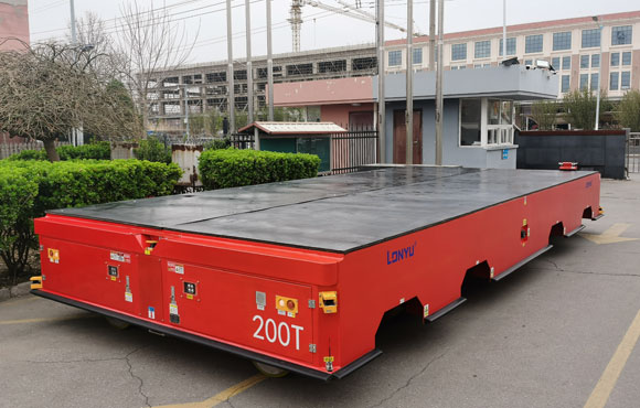
After defining the load, rack interface, and operating route, buyers can compare these requirements with a specific machine configuration. The following specifications describe Lonyu’s automatic mold transfer system.
| Key information | Published specification |
| Rated load capacity | 10 tons |
| Vehicle weight | 2.2 tons |
| Vehicle dimensions | 2,580 × 1,600 × 675 mm |
| Lifting method | Hydraulic cylinder platform lift |
| Navigation options | Magnetic strip, Laser SLAM, or QR code |
| Turning radius | 1,500 mm |
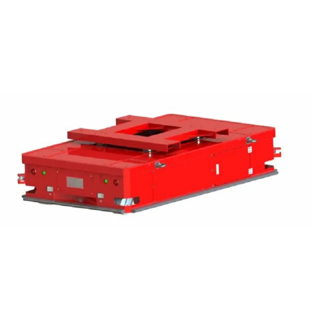
Hydraulic Lifting for Under-Rack Mold Pickup
The vehicle is designed to enter beneath a rack with supporting legs. After reaching the pickup position, its hydraulic cylinder platform lift raises the load.
This arrangement is useful when a mold is stored on a raised support structure and needs to be moved without first transferring it to a separate trolley. Buyers should compare the vehicle outline with the rack’s internal opening and confirm the platform’s contact position using the rack drawing.
The actual lifting stroke and contact arrangement should also be confirmed before ordering. The rack must provide enough clearance for entry, while the platform must lift the load without pressing against the rack structure.
Navigation Options for Different Factory Routes
The available navigation choices include magnetic strip, Laser SLAM, and QR code. Each can be assessed against the workshop layout and transport sequence.
For a fixed route between production areas, magnetic guidance may be sufficient. If the route needs more flexibility, laser-based navigation may be worth assessing. QR-code guidance can be considered where station markers can be installed and maintained.
The navigation method should be confirmed before the factory floor is prepared. This avoids installing guidance markers or floor routes that do not match the final vehicle configuration.
Dual-Drive Structure and Vehicle Layout
The vehicle uses a dual-drive structure and has overall dimensions of 2,580 × 1,600 × 675 mm. Its published turning radius is 1,500 mm.
The drive structure is one part of the mechanical configuration, while the dimensions and turning radius help buyers assess access to aisles and workstations. During technical review, compare the vehicle outline with the narrowest route section, rack approach, and station layout. The supplier should also clarify the drive arrangement and its operating requirements.
A Transfer Workflow for Foundry Operations
The described application connects mold movement between a melting area and a shakeout area, with a buffer area between them. The vehicle transports the mold rack or load to the next stage, while an empty pallet can return to the melting area.
This workflow can reduce repeated manual movement between separated process areas. It also creates a defined route for loaded deliveries and empty returns. The actual station sequence, rack design, and handoff method should be confirmed during layout planning.
For foundries handling heavy molds, a heavy duty agv can help organize repeated transfers between process stages. As part of the plant’s material handling equipment, its value depends on how well it fits the rack, route, and production sequence—not simply on its rated capacity.
Frequently Asked Questions About Mold Transfer Carts
What Is the Rated Load Capacity of This Automatic Mold Transfer System?
The published rated load capacity is 10 tons. Buyers should confirm that the figure covers the complete lifted load, including the mold and any supporting rack or fixture. Load distribution and support positions should also be reviewed before finalizing the configuration.
Can This Vehicle Pick Up a Mold Rack from Underneath?
The design uses a hydraulic lifting platform and is intended to enter beneath a rack with supporting legs. Whether it fits a particular rack depends on the clear opening, underside height, support-leg positions, and lifting contact points. These dimensions should be checked against the rack drawing.
Which Navigation Methods Are Available for This Model?
The published options are magnetic strip, Laser SLAM, and QR code. The preferred method should be selected after reviewing route stability, station locations, floor conditions, and the need for future route changes.
How Much Capacity Should a Mold Transfer Cart Have?
Start with the heaviest complete load, including the mold, pallet, rack, and fixtures carried during transport. Then check the center of gravity and load distribution. The selected rated capacity must cover the complete load without exceeding the vehicle’s specified limit.
What Measurements Are Needed Before Selecting a Cart?
Record the load weight and dimensions, center of gravity, rack opening, support-leg spacing, underside clearance, pickup and delivery heights, aisle width, and turning space. A floor plan and rack drawing help the supplier check whether the vehicle can complete the entire transfer.
Conclusion
A successful mold-handling arrangement depends on how well transportation fits into the production sequence. If molds move between several process stages, poorly coordinated handoffs can create waiting time, repeated handling, and unnecessary movement of empty carriers.
A planned route can connect pickup points, buffer areas, and delivery stations into a more consistent flow. For foundries, this means considering not only how a mold reaches the next process, but also how empty pallets return and how each station is kept ready for the next load.
Lonyu’s configuration can be evaluated against these workflow requirements using the mold drawing, rack dimensions, and factory layout. The aim is to confirm that the vehicle fits the actual handling process before equipment is selected.